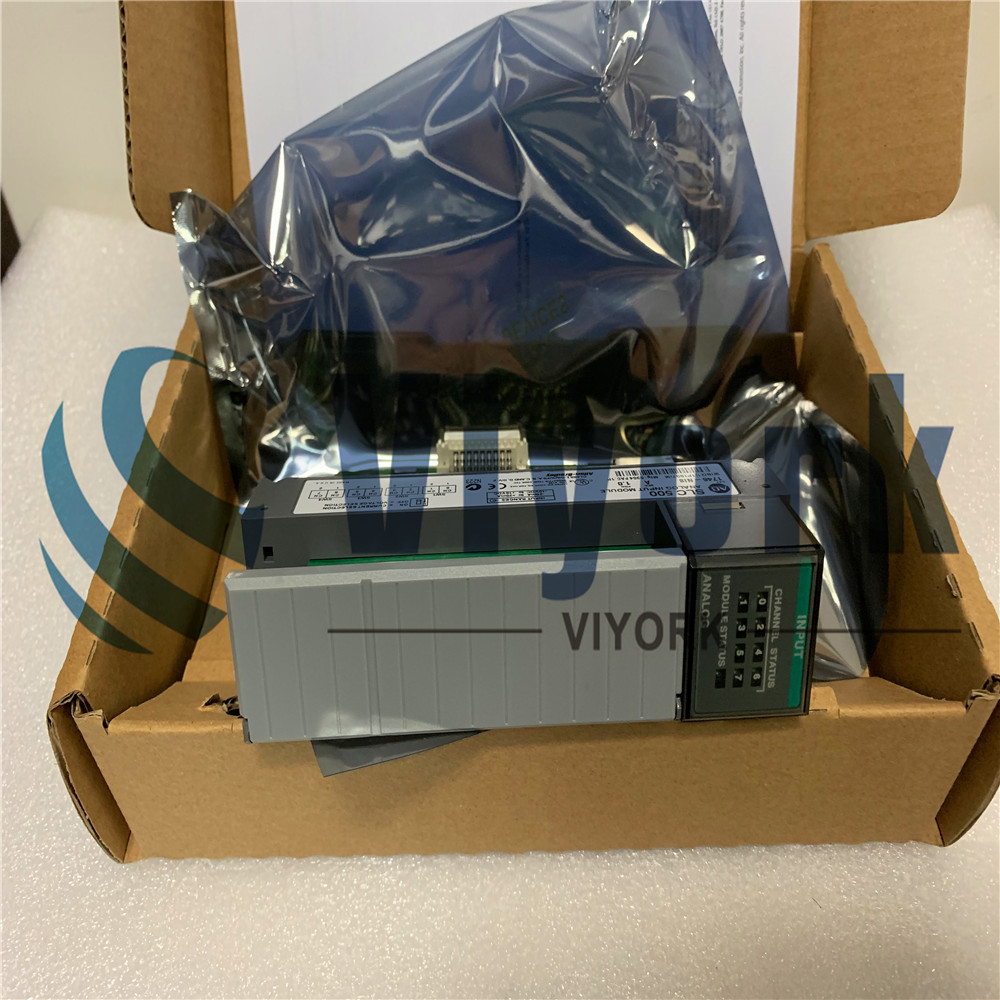
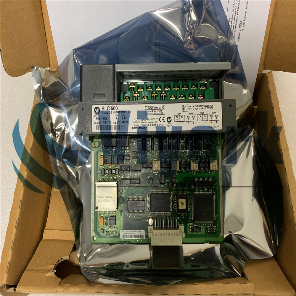
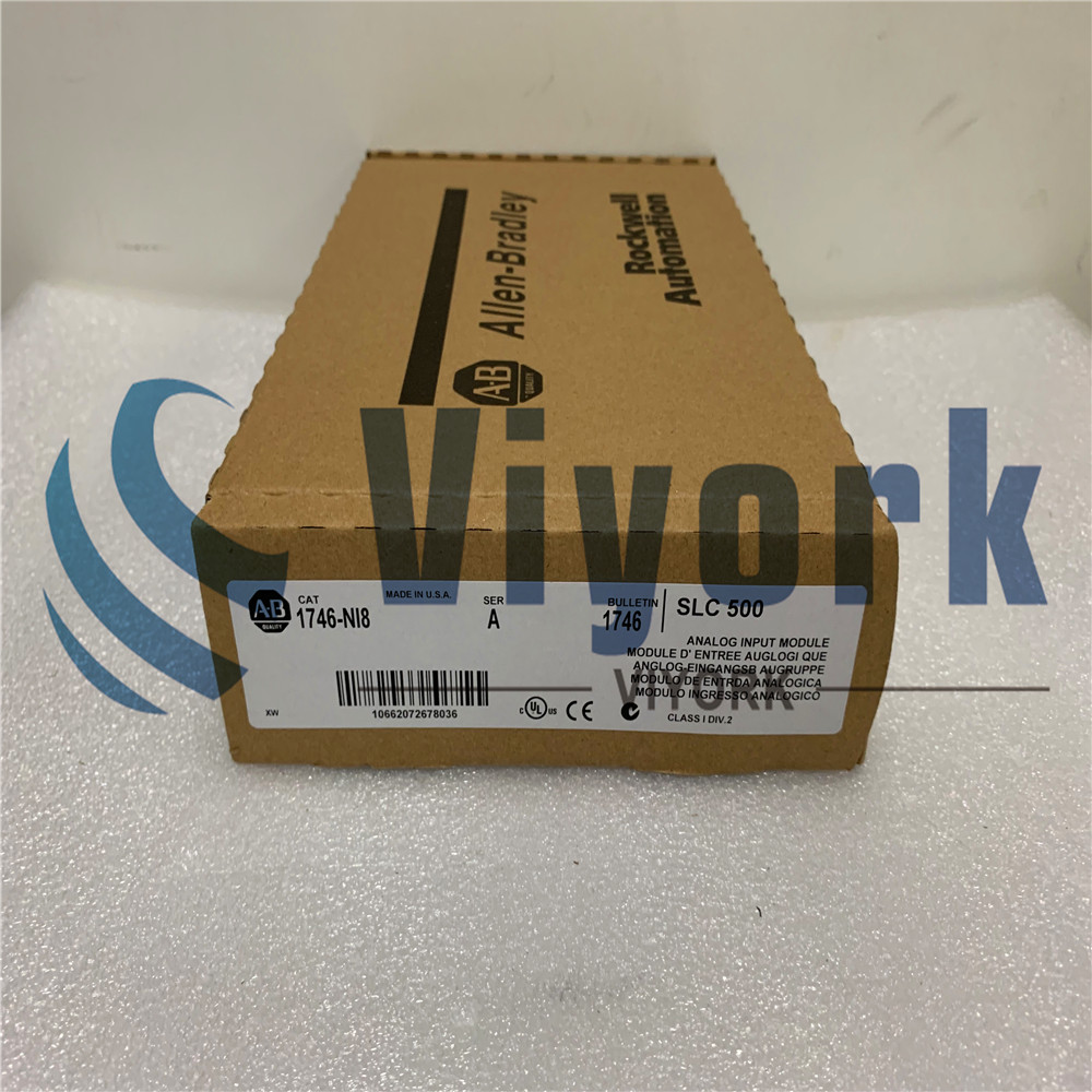
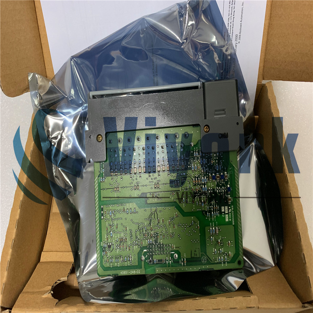
AB Analog I0 Module 1746-NI8
Product Specification
| Brand | Allen-Bradley |
| Part Number/Catalog No. | 1746-NI8 |
| Series | SLC 500 |
| Module Type | Analog I/O Module |
| Backplane Current (5 Volts) | 200 milliamps |
| Inputs | 1746-NI4 |
| Backplane Current (24 Volts DC) | 100 milliamps |
| Input signal Category | -20 to +20 mA (or) -10 to +10V dc |
| Bandwidth | 1-75 Hertz |
| Input Filter Frequencies | 1 Hz, 2 Hz, 5 Hz, 10 Hz, 20 Hz, 50 Hz, 75 Hz |
| Update Time | 6 milliseconds |
| Chassis location | Any I/O module slot except slot 0 |
| Resolution | 16 bits |
| Backplane Current | (5 Volts) 200 mA;(24 Volts DC) 100 mA |
| Step Response | 0.75-730 milliseconds |
| Conversion type | Successive approximation, switched capacitor |
| Applications | Combination 120 Volts AC I/O |
| Input Types, Voltage | 10V dc 1-5V dc 0-5V dc 0-10V dc |
| Backplane Power Consumption | 14 Watts Maximum |
| Input Type, Current | 0-20 mA 4-20 mA 20 mA 0-1 mA |
| Input Impedance | 250 Ohms |
| Data Format | Engineering Units Scaled for PID Proportional Counts (-32,768 to +32,767 range), Proportional Counts (User Defined Range, Class 3 only). 1746-NI4 Data Form |
| Cable | 1492-ACABLE*C |
| LED Indicators | 9 green status indicators one for each of 8 channels and one for module status |
| Thermal Dissipation | 3.4 Watts |
| Wire Size | 14 AWG |
| UPC | 10662072678036 |
| UNSPSC | 32151705 |
About 1746-NI8
It has a maximum backplane power consumption of 1 Watt at 5 Volts DC and 2.4 Watts at 24 Volts DC. The 1746-NI8 can be installed in any I/O slot, except Slot 0 of the SLC 500 I/O chassis. Input signal data is converted to digital data via successive approximation conversion. The 1746-NI8 module uses programmable filter frequencies with a low-pass digital filter for input filtering. It performs continuous autocalibration and has an isolation voltage of 750 Volts DC and 530 Volts AC, tested for 60 seconds. It has a common-mode voltage ranging from -10 to 10 Volts with a maximum of 15 Volts between any two terminals.


Product Description
The 1746-NI8 module comes with a removable terminal block of 18 positions. For wiring, the Belden 8761 or a similar cable must be used with one or two 14 AWG wires per terminal. The cable has a maximum loop impedance of 40 Ohms at the voltage source and 250 Ohms at the current source. For troubleshooting and diagnostics, it has 9 green LED status indicators. The 8 channels have one indicator each to display the input status and one each for displaying the module status. The 1746-NI8 has a Division 2 hazardous environment standard with an operating temperature of 0 to 60 degrees Celsius.

The 1746-NI8 features Eight (8) channel analog input module compatible for used with SLC 500 Fixed or modular hardware style controllers. This module from Allen-Bradley has individually selectable voltage or current input channels. Available selectable input signals include 10V dc, 1–5V dc, 0–5V dc, 0–10V dc for Voltage while 0–20 mA, 4–20 mA, +/-20 mA for Current.
Input signals may be represented as Engineering Units, Scaled-for-PID, Proportional Counts (–32,768 to +32,767 range), Proportional Counts with User Defined Range (Class 3 only) and 1746-NI4 Data.
This Eight (8) channel module is compatible for use with SLC 5/01, SLC 5/02, SLC 5/03, SLC 5/04 and SLC 5/05 processors. SLC 5/01 may only operate as class 1 while SLC 5/02, 5/03, 5/04 are configurable for Class 1 and Class 3 operation. The channels of each module may be wired in single-ended or differential input.
Product Features
This module has a removable terminal block for connection to input signals and easy replacement of module without the need of rewiring. Selection of input signal type is done with the use of embedded DIP switches. DIP switch position must be in accordance to the software configuration. If the DIP switch settings and the software configuration differs, a module error will be encountered and will be reported in the diagnostic buffer of the processor.
The programming software that is used with the SLC 500 product family is RSLogix 500. It is a ladder logic programming software that is also used to configure majority of modules in the SLC 500 product family.


