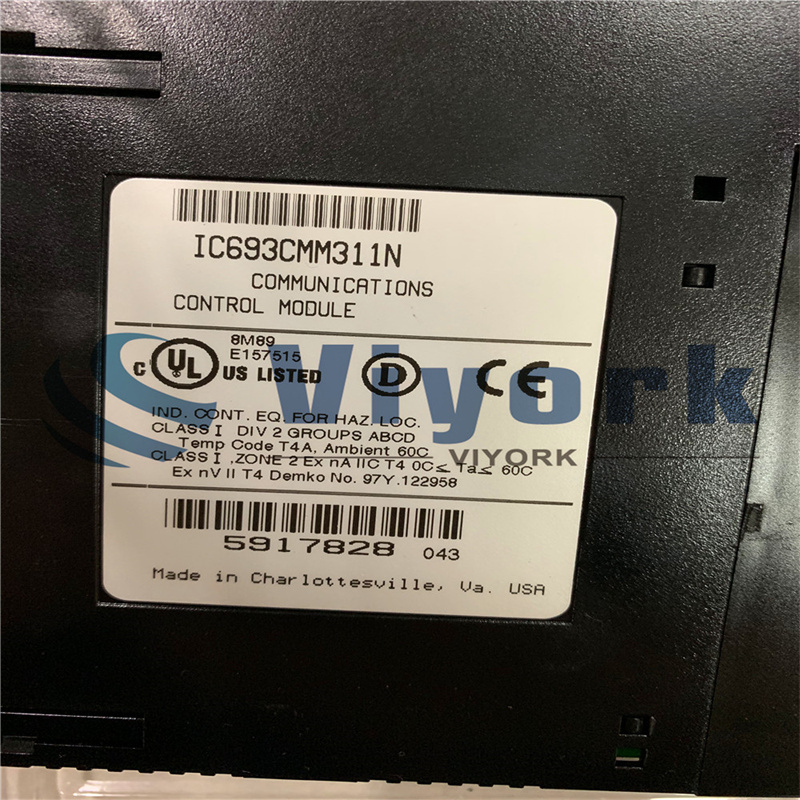
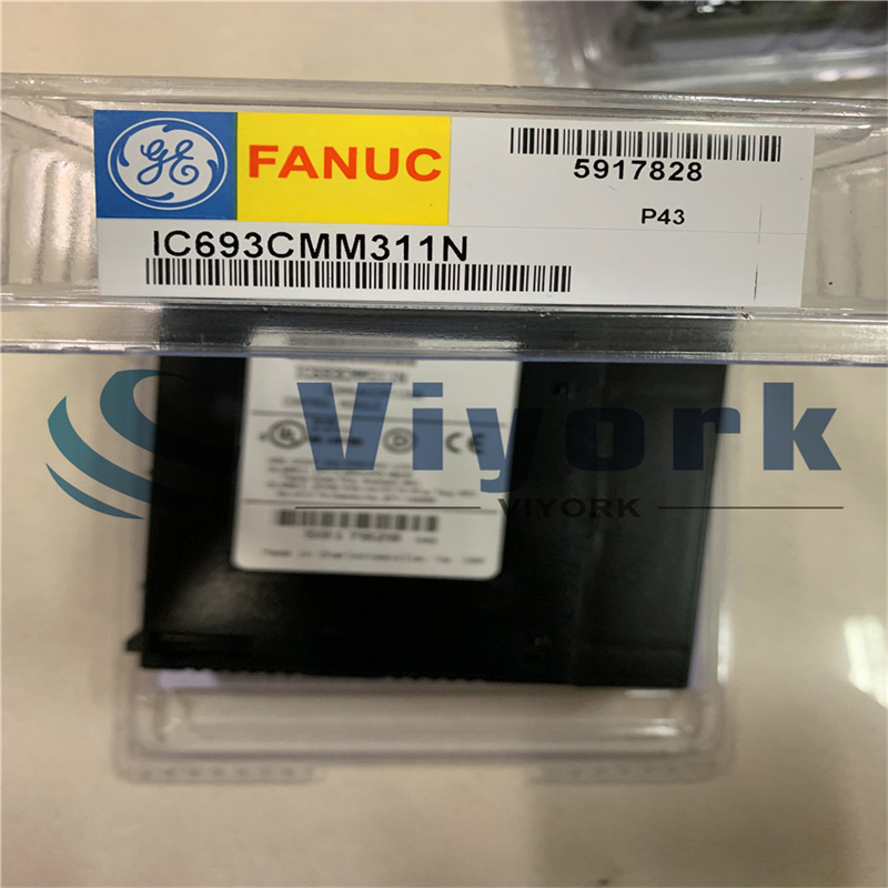
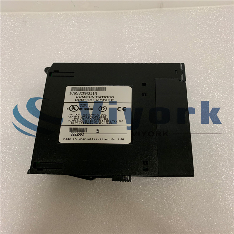
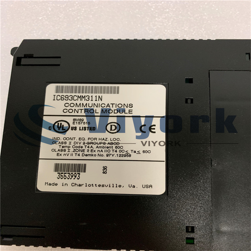
GE Communications Module IC693CMM311


Product Description
The GE Fanuc IC693CMM311 is a Communications Coprocessor Module. This component provides a high performance coprocessor for all Series 90-30 modular CPUs. It cannot be used with embedded CPUs. This covers models 311, 313, or 323. This module supports GE Fanuc CCM communications protocol, the SNP protocol and the RTU (Modbus) slave communications protocol. It is possible to configure the module using the configuration software. Alternatively, users can opt for a default setup. It has two serial ports. Port 1 supports RS-232 applications while Port 2 supports either RS-232 or RS-485 applications. Both ports are wired to the module’s single connector. For this reason, the module has been supplied with a wye cable (IC693CBL305) in order to separate the two ports to make wiring easier.
It’s possible to use up to 4 Communications Coprocessor Modules in a system that has a CPU of 331 or above. This can only be done via the CPU baseplate. In versions before 4.0, this module presents a special case when both ports are configured as SNP slave devices. The ID value –1 in a Cancel Datagram request received at either slave device will end up cancelling all established Datagrams on both slave devices within the same CMM. This is different to a CMM711 module, which has no interaction between datagrams established on the serial ports. Version 4.0 of the IC693CMM311, which was released in July 1996, solved the issue.
Technical Specifications
| Module Type: | Communications Co-Processor |
| Communication Protocols: | GE Fanuc CCM, RTU (Modbus), SNP |
| Internal Power: | 400 mA @ 5 VDC |
| Comm. Ports: | |
| Port 1: | Supports RS-232 |
| Port 2: | Supports either RS-232 or RS-485 |
Technical Information
Except for the serial port connectors, the user interfaces for the CMM311 and CMM711 are the same. The Series 90-70 CMM711 has two serial port connectors. The Series 90-30 CMM311 has a single serial port connector supporting two ports. Each of the user interfaces are dis- cussed below in detail.
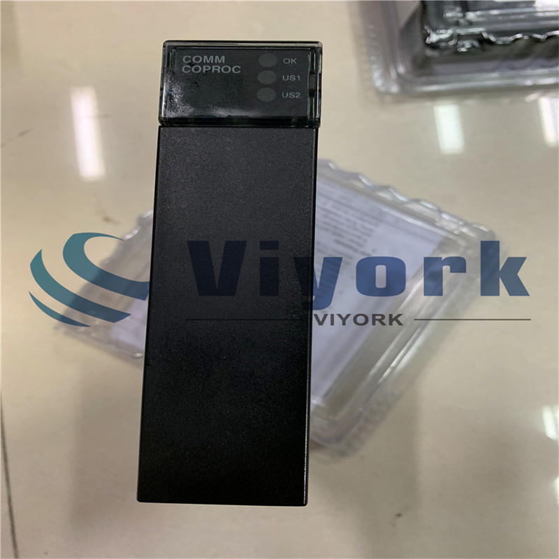
The three LED indicators, as shown in the figures above, are located along the top front edge of the CMM board.
Module OK LED
The MODULE OK LED indicates the current status of the CMM board. It has three states:
Off: When the LED is off, the CMM is not functioning. This is the result of a hardware mal- function (that is, the diagnostic checks detect a failure, the CMM fails, or the PLC is not pres- ent). Corrective action is required in order to get the CMM functioning again.
On: When the LED is steady on, the CMM is functioning properly. Normally, this LED should always be on, indicating that the diagnostic tests were successfully completed and the configuration data for the module is good.
Flashing: The LED flashes during power-up diagnostics.
Serial Port LEDs
The remaining two LED indicators, PORT1 and PORT2 (US1 and US2 for the Series 90-30 CMM311) blink to indicate activity on the two serial ports. PORT1 (US1) blinks when port 1 either sends or receives data; PORT2 (US2) blinks when port 2 either sends or receives data.
Serial Ports
If the Restart/Reset pushbutton is pressed when the MODULE OK LED is on, the CMM will be re-initialized from the Soft Switch Data settings.
If the MODULE OK LED is off (hardware malfunction), the Restart/Reset pushbutton is inop- erative; power must be cycled to the entire PLC for CMM operation to resume.
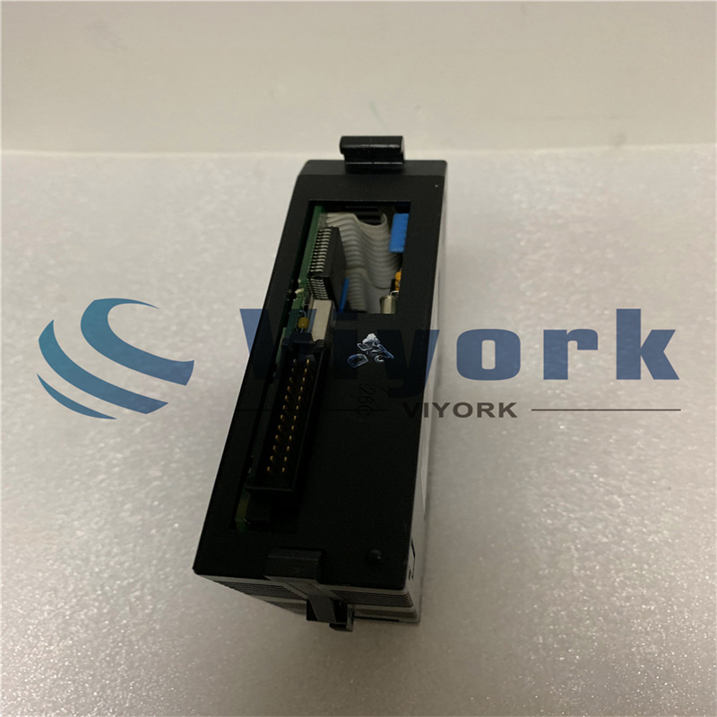
The serial ports on the CMM are used to communicate with external devices. The Series 90-70 CMM (CMM711) has two serial ports, with a connector for each port. The Series 90-30 CMM (CMM311) has two serial ports, but only one connector. The serial ports and connectors for each PLC are discussed below.
Serial Ports for the IC693CMM311
The Series 90-30 CMM has a single serial connector which supports two ports. Port 1 applica- tions must use the RS-232 interface. Port 2 applications can select either the RS-232 or
RS-485 interface.
NOTE
When using the RS-485 mode, the CMM can be connected to RS-422 devices as well as RS-485 devices.
The RS-485 signals for port 2 and the RS-232 signals for port 1 are assigned to the standard connector pins. The RS-232 signals for port 2 are assigned to normally unused connector pins.
IC693CBL305 Wye Cable
A Wye cable (IC693CBL305) is supplied with each Series 90-30 CMM and PCM module. The purpose of the Wye cable is to separate the two ports from a single physical connector (that is, the cable separates out the signals). In addition, the Wye cable makes cables used with the Se- ries 90-70 CMM fully compatible with the Series 90-30 CMM and PCM modules.
The IC693CBL305 Wye cable is 1 foot in length and has a right angle connector on the end that connects to the serial port on the CMM module. The other end of the cable has dual connec- tors; one connector is labeled PORT 1, the other connector is labeled PORT 2 (see figure be- low).
The IC693CBL305 Wye cable routes the Port 2, RS-232 signals to the RS-232 designated pins. If you do not use the Wye cable, you will need to make a special cable to connect RS-232 de- vices to Port 2.
Products categories
-

Phoenix Contact 2966595 Octocoupler Terminal Bl...
-

ORIENTAL MOTOR VEXTA ASD16A-S LOOP DRIVER CLOSE...
-

GE IC693PCM311 PROGRAMMABLE COPROCESSOR MODULE ...
-

FESTO ADVU16-20-P-A COMPACT CYLINDER WITHOUT PR...
-

ORIENTAL MOTOR VEXTA ASD18A-K STEPPER DRIVE 1.7...
-

GE IC693MDL730 POSITIVE LOGIC OUTPUT MODULE 8 O...